 |
|||
| . | |||
|
1. Adjuster Cap 2. Chain Cover Bolt 3. Chain Cover 4. Chain 5. Sprocket 6. Pad Wear Warning Indicator Pin 7. Secondary Adjuster Asssembly 8. Primary Adjuster Assembly 9. Housing 10. Needle Bearing 11. Side Plug |
12. Short Guide Sleeve Bolt 13. Short Guide Sleeve 14. Short Guide Sleeve Bush 15. Long Guide Sleeve End Cap 16. Long Guide Sleeve Bolt 17. Long Guide Sleeve 18. Brass Bush 19. Guide Sleeve Boot 20. Guide Sleeve Boot Washer 21. Pad Retainer 22. Pad Retainer Clip |
23. Pad Retainer Washer 24. Pad Retainer Pin 25. Lever Assembly 26. Lever Roller 27. Actuation Block 28. Piston 29. Return Spring 30. Tappet Bush 31. Secondary Seal 32. Cover Plate 33. Tappet Boot Assembly |
34. Cover Plate Bolt 35. Air Chamber 36. Inboard Pad 37. Outboard Pad 38. Carrier 39. Brake Disc 40 Hub Assembly |
L Series (Knorr Calipers)
Actuation
| Brake Actuation | On Stroke |
→ |
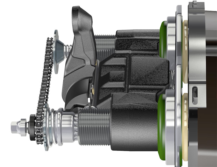
The pushrod of the air chamber (35) moves the lever (25), which rotates in the needle bearings (10) to transfer and amplify the input force via the lever roller (26) to the actuation block (27). The output force is distributed by the actuation block and the pistons (28) to the tappet head assemblies (33) and through to the inboard pad (36). After the pistons travel through the running clearance between the pad (36) and the disc (39), the caliper slides on the guide sleeves (13 and 17) to transfer the reaction force to the outboard pad (37) and clamp both pads (36 & 37) against the brake disc (39) to generate the braking force.
| Brake Release | Off Stroke | ← |
On brake release the return springs (29) push back the actuation block, pistons and the tappet head assemblies. Simultaneously the lever returns to the start position leaving a defined running clearnance between the pads and disc.
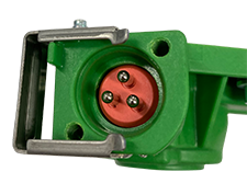
| Pad Wear Sensing | (where applicable) |
 |
 |
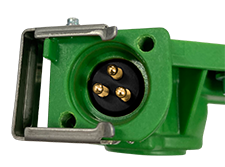 |
If the brake is fitted with an electrical pad wear sensor within the chain cover (3) then the brake adjustment for pad wear rotates the secondary adjuster (7) to drive the sensor and send an electrical signal to the vehicle to monitor wear and / or indicate when the pads need replacing.
Adjustment
| Pre-set Running Clearance Phase | On Stroke | → |
During the on stroke the lever moves forwards and, as it rotates, the drive fingers (25a) move through the pre-set running clearance on the one way clutch housing (8a) of the primary adjuster (8). If no adjustment is required - i.e. the pads (36 &37) are now touching the disc (39) - the piston is under load and cannot turn.
| Adjustment Phase | On Stroke | → |
If there is excess clearance (wear), meaning the pads are not yet touching the disc, the lever will continue to rotate forwards. The lever continues to rotate and the drive fingers move the one way clutch housing in the drive direction. The one way clutch housing is engaged with the drive sleeve (8c) and so the piston will turn until the pads contact the disc. The chain (4) that connects the primary and secondary adjuster (7) ensures that both pistons turn simultaneously.
| Elasticity Phase | On Stroke | → |
When the pads contact the disc a clamp force is generated and the pistons are under load. The lever continues to move forwards due to deflection in the brake housing (elasticity). The one way clutch mechanism continues to drive but due to the high load the pistons cannot turn. Under load the overload clutch (8b) disengages the one way clutch housing from the drive sleeve. This ensures there is no adjustment made due to elasticity and prevents high load from damaging the adjustment mechanism.
| Return Phase | Off Stroke | ← |
During the off stroke the lever moves backwards and the overload clutch re-engages the drive sleeve with the one-way clutch housing. As the lever continues to move backwards the drive fingers return through the pre-set running clearance on the one way clutch housing. If no adjustment has taken place the lever is now at rest. If adjustment has taken place the lever continues to its rest position. The drive fingers continue to push the one way clutch housing which is now in the slip direction. Therefore there is no rotation of the drive sleeve and the piston cannot de-adjust.
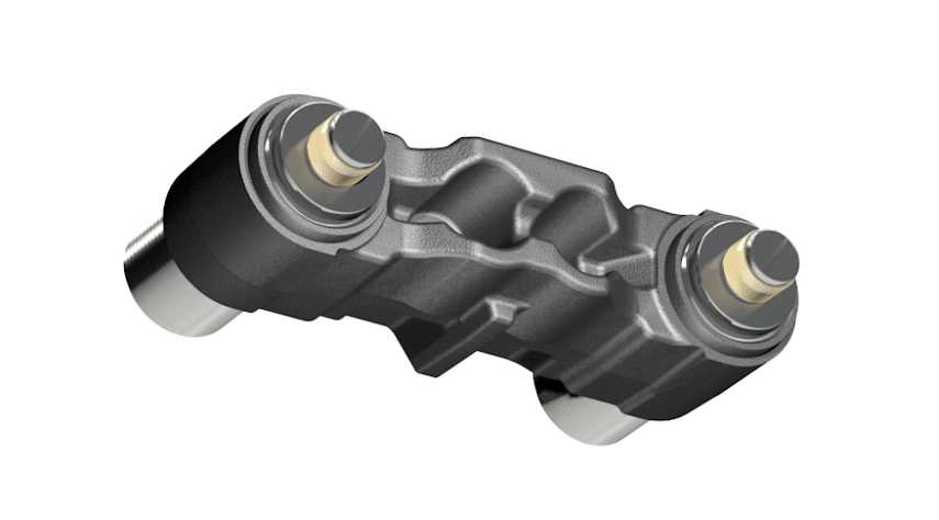
N Series Calipers (Meritor)
Adjustment
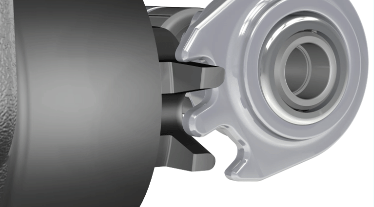
Pre-set Running Clearance Phase
During the on stroke, the lever (XX) moves forwards and as it rotates, the ball-ended pin (XXa) moves through the pre-set running clearance on the slotted shaft (Xa) of the adjuster (X).
If no adjustment is required i.e. the pads (36, 37) are now touching the disc (39), the piston drives (YY) are under load and cannot turn.
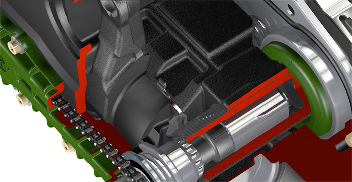
Adjustment Phase
If there is excess clearance (wear) meaning the pads are not yet touching the disc, the lever will continue to move forwards.
The lever continues to rotate and the ball-ended pin moves the adjuster shaft in the drive direction.
The adjuster shaft is engaged with the adjuster gear (Xc) and so the piston drive will turn until the pads contact the disc.
The adjuster gear which connects both of the piston drives (YY) ensures both pistons move simultaneously.
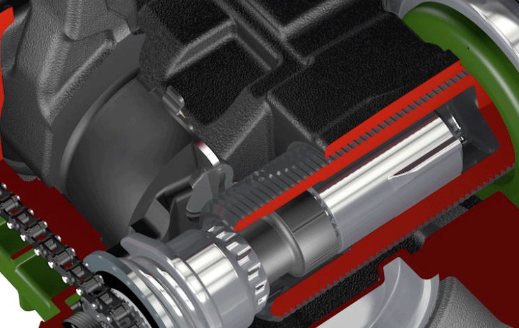
Elasticity Phase
When the pads contact the disc a clamp force is generated and the pistons are under load.
The lever continues to move forwards due to deflection in the brake housing (elasticity).
The one way clutch mechanism continues to drive but due to the high load the pistons cannot turn. Under load the overload clutch (Xb) disengages the adjuster shaft from the adjuster gear.
This ensures there is no adjustment made due to elasticity and prevents high load from damaging the adjustment mechanism.
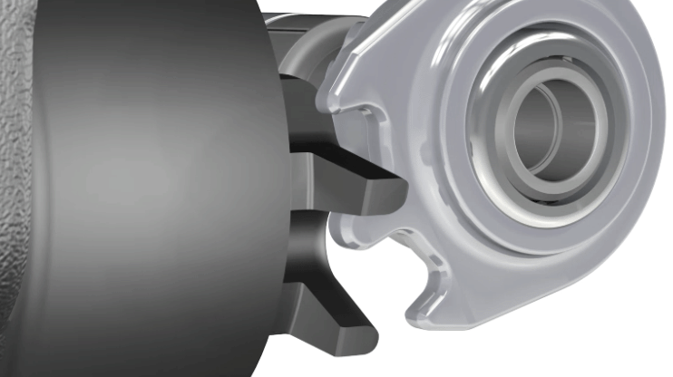
Return Phase
During the off stroke the lever moves backwards and the overload clutch re-engages the adjuster gear with the adjuster shaft.
As the lever continues to move backwards the ball-ended pin returns through the pre-set running clearance on the slotted shaft.
If no adjustment has taken place the lever is now at rest. If adjustment has taken place, the lever continues to its rest position.
The ball-ended pin continues to push the slotted shaft which is now in the slip direction. Therefore there is no rotation of the adjuster gear and the piston drives cannot de-adjust.